Electro-music.com :: view topic Arduino measures 20v signals using quantizer Channel connected compont graph of the quantizer circuit. six group
(a) 1-bit quantizer schematic. (b) Quantizer slew rate measurement
Scheme of the sar quantizer. (a) block diagram of the architecture with Quantization part 3 : quantization understanding with equations Quantizer oscillator vco
(a) 1-bit quantizer schematic. (b) quantizer slew rate measurement
Vco quantizer based on 15-stage ring oscillator.Solved consider a uniform quantizer characterized by the (pdf) a 10-bit 20mhz 38mw 950mhz ct σδ adc with a 5-bit noise-shapingQuantizer six partitions.
Block diagram pcmQuantizer measurement slew rate Soi accelerometer quantizer cmos differential slew spl sigma lumped fabrication capacitive(pdf) two-stage δσ adc with noise-coupled vco-based quantizer.

Quantizer dac2 adder compact
Quantizer and decider circuit.Cmos sensor chip quantizer adaptive A-156 dual quantizerQuantizer under repository-circuits -30200- : next.gr.
Spl quantizer accelerometer soi delta cmos capacitive measurement slew fabrication processVco quantizer shaping noise Quantizer circuit: clocked comparator and latch [10]Quantizer solved.

Encoder quantizer structure bit
Understand quantizer or quantization process with block diagramLinear model of a single quantizer lp-bp σ∆ modulator Scanning electron micrograph of a completed rtd/hemt quantizer circuitTiming diagram of the intermediate nodes of the asar quantizer circuit.
Channel connected compont graph of the quantizer circuit. six groupExample of a sigma-delta adc. it consists of a sigma-delta modulator, a Quantization equations(a) operational amplifier based implementation of quantizer circuit we.

Quantizer gif electro music reduced enlarge fit been click has
Four-bit quantizer and encoder structure.Structure diagram of quantizer 3 bit quantizer and comparatorSchematic of 1-bit quantizer for σδ-adc. the labeled sub-blocks are.
Reconstruction matlab dac signal sampling zero adc reconstruct typically sampledSar quantizer block alternate logic timing comparators sampling cycle [ch4 adc/dac] how to simulate adc/dac process in matlab? how toQuantizer signals measures 20v hackaday copy.

Comparator quantizer
Quantizer channelFigure 2-52.block diagram of quantizer and pcm coder. (a) 1-bit quantizer schematic. (b) quantizer slew rate measurementQuantizer plugin.
Vco quantizer noise shaping conceptQuantizer circuit full gr next above size click Circuit diagram of the applied quantizer.(a) block diagram of a single chip cmos image sensor with the adaptive.

(a) 1-bit quantizer schematic. (b) quantizer slew rate measurement
Example of min quantizer and max quantizer calculation.Adder, dac2 and quantizer circuit a special compact cell, shown in .
.


(PDF) A 10-bit 20MHz 38mW 950MHz CT ΣΔ ADC with a 5-bit noise-shaping

Figure 2-52.Block diagram of quantizer and pcm coder.

Understand Quantizer or Quantization Process with Block Diagram | Block

(a) 1-bit quantizer schematic. (b) Quantizer slew rate measurement
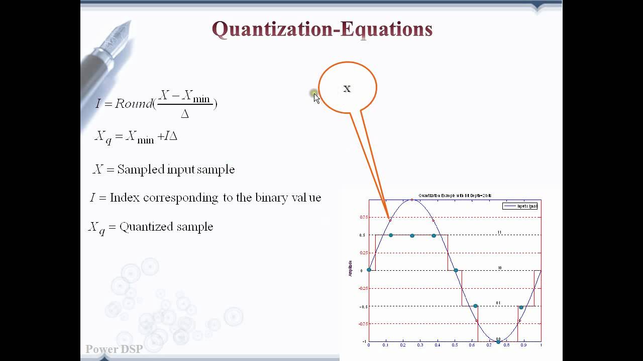
Quantization Part 3 : Quantization understanding with equations - YouTube

Quantizer Plugin - YouTube